|
RS232 to TTL logic board
As outlined above the RS232 converter is based around the MAX232 device, the circuit includes LED drivers to indicate Tx and Rx data and a 100mA +5V regulator. Data Out is supplied at +5V and +3.3V logic levels via a potential divider.Here the Data In input will work for +5V & +3.3V logic levels, as according to the data sheets available online a standard production MAX232 has an true state input logic threshold of approximately 2V.
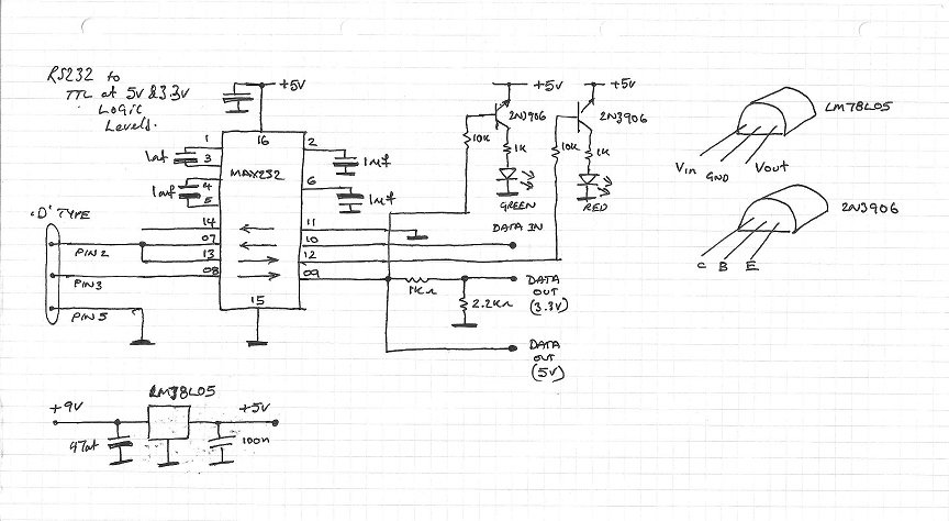
The circuits stripboard layout was then laid down on paper,
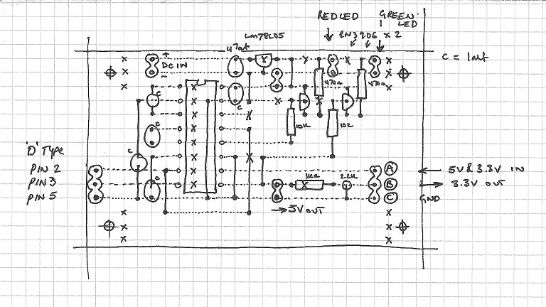
and constructed for testing.

BT Module support board
The BT module support board is in reality just a power supply and configuration link to allow the modules parameters to be changed.
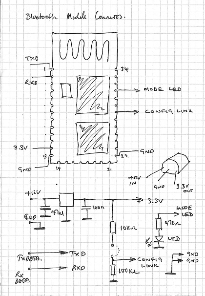
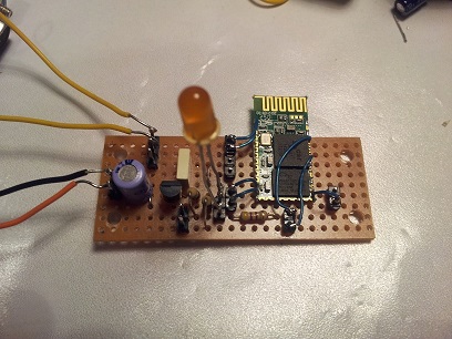
Once again the design was planned out for constructed on stripboard,
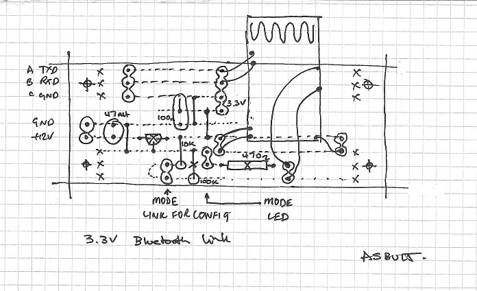
then assembled.
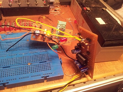
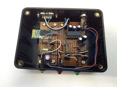
Finally the two boards were connected together, tested and transferred into a suitable case.
Creating a test connection from a mobile phone to a PC.
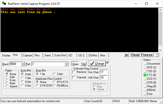
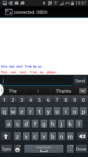
The only thing remaining is to test the unit from end to end, for this I used "Bluetooth Terminal" on an android device and "RealTerm" on the PC (see links below). Once the bluetooth module was paired with the phone it was possible to send data to and from the PC to the phone.
|