|
As well as encoding digital I/O and Analogue Inputs with the GPC(b)/uMODBUS(s) project it was also desired that pulsed inputs should be readable by the core in order to make use of this information remotely.
Basic frequency(or pulses per second) and simple RPM measurement would then be possible. This function could be achieved by utilising the internal microcontrollers Timer/Counter.
In order to accumulate pulses normally the internal code would be written in such a way as
to regularly clear and then read the contents of the counter at regular intervals determined
by either interrupt or loop timers.
However in this project use has already been made of interrupts and timed loops in order to service the internal UART to maintain reliable MODBUS communications.
To this end it was decided to construct a separate pulse gate circuit that could manage the timing
and gating of the pulses autonomously and not have to rely on internal timers, that may be perturbed during the regular read write cycles operating within the core.
This first revision utilises a 555 timer placed into monostable mode and can be set to gate at 1 or 0.6 second intervals.

The circuit is designed to work as follows, once the microcontroller has cleared down its internal
counter a pulse is sent from the controller to reset the monostable and open the gate (START IN).
Once the monostable is active pulses present at the transistor isolated input (PULSE IN) are passed though to the output into the microcontrollers counter (PULSE OUT).
Once the monostable time expires the gate closes and the pulses to the microcontroller are interrupted, feedback is given to the microcontroller(RUNNING)in order for it to identify that counting has ended and that the contents are valid.
As mentioned above the circuit can be set to gate to 1 second or 0.6 seconds, the 0.6 second gate being used when measuring RPM.
This narrow gating time was calculated as follows, for example if a shaft is connected to a suitable sensor so that one pulse is produced per revolution then if the shaft is set to rotate at 100 revolutions in one minuet then this will produce a pulse every 1.67 seconds. The pulses generated over one second can simply calculated from:

If we now consider we wish to balance both sites of the equation so that the number of pulses received are related to the input RPM speed so that no further processing is required. If we gate over a shorter time we will drop the measured resolution of the counter but attain the required effect, to this end if we gate at 0.6 seconds the output will be a scaled value of the input speed. This can been written as:
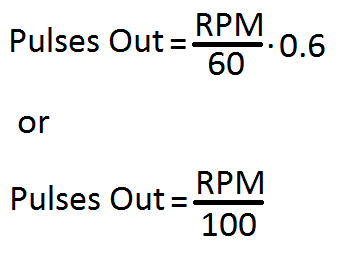
In table form this appears as below and demonstrates the measured speed when a gating time of 0.6 seconds is used will be in x100 RPM:

Keeping Time:
the values of the components for the monostable can be calculated by using the formula provided on the 555 timer datasheet.

here if we fix the capacitor value to 47uf then by substitution and transposition the values of R with respect to t can be found as:

we can now find the required values of R as:
for t=1s,
R would be 19,342ohms or from N.P.Vs 18Kohm+1.2Kohm = 19.2Kohm
and for t=0.6s,
R would be 11,605ohms or again from N.P.Vs 10Kohm+1.5Kohm = 11.5Kohm
These values where then tested to verify a reasonable gate was generated.
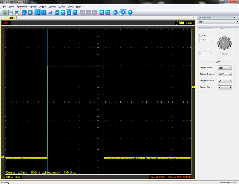
When R=11.5Kohm a reasonable 0.6s gate time was observed.
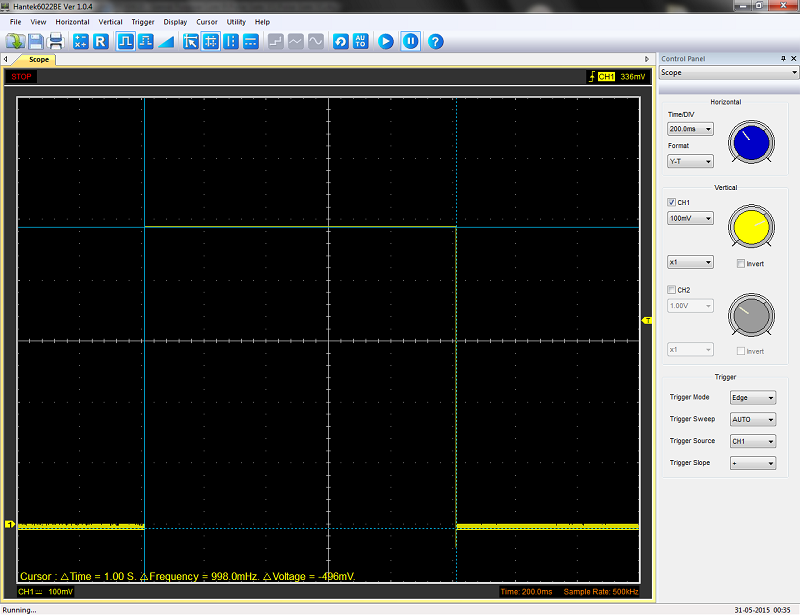
Additionally when R=19.2Kohm a reasonable 1.0s gate time was observed.
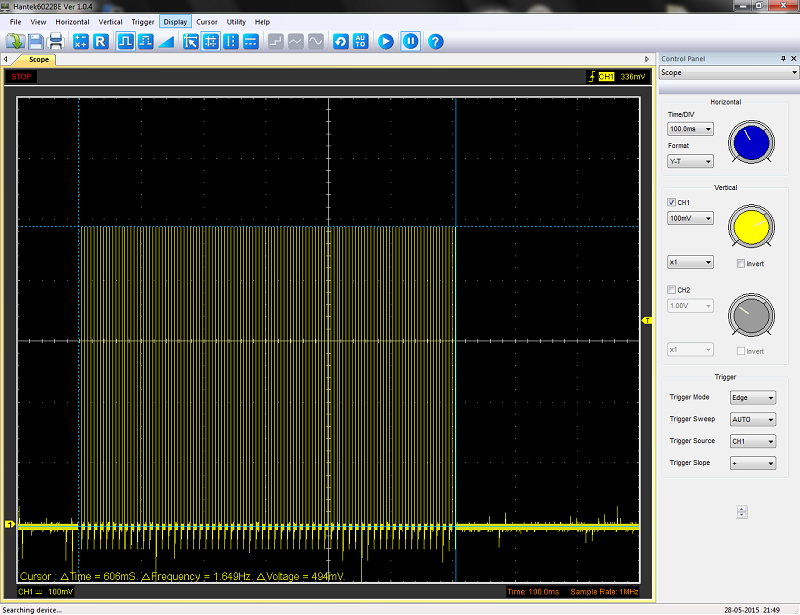
When operating the pulsed outputs from the gate circuit generates a stream of pulses into the counter while the gate is open.This was measured while the device was operating and can be seen below:
Now the design was reasonably outlined the circuit was transferred onto stripboard.

Then constructed for testing.
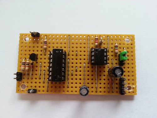
The circuit requires a the following signals in order to function, these need to be implemented in order for the GPC(b)to operate the pulse counter correctly:

|