|
In order to carry out the development of some analogue op-amp circuity
a low cost positive and negative voltage source was required.
To this end the negative voltage source developed some time ago has been modified
to improve overall efficiency and increase power output on the negative rail.
Ideally it was hoped that +/-5V @100mA could be attained from the design and after few
tweaks the previous circuit was modified as below.
Circuit:
%20-%20small.png)
Here most notably the base resistors of the 2N3904 voltage switches have been decreased
in order to improve reservoir capacitor charging times and the frequency of the primary
oscillator has been tuned for maximum negative voltage generation at load.
Circuit Performance:
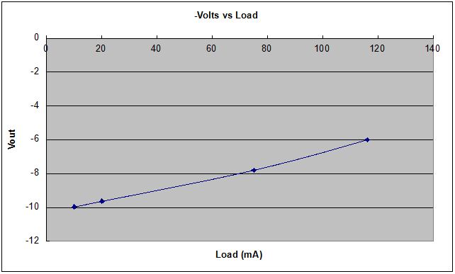
During tests as the load on the negative voltage generator increased as expected the
output voltage deceased as below. Here if a conventional -5V regulator with a drop-out
voltage of about 1.1 V was used, it would cease to function properly when a load of >110mA
is demanded from the circuit.
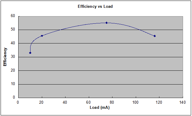
Over the same load ranged the conversion efficiency is as below, peaking at about 55% at 70mA Load.
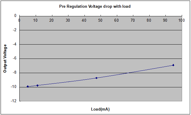
By connecting a -5 volt regulator to the converter and applying the load
to the output of the regulator the resulting voltage drop on the unregulated
and regulated voltages can be measured.
Pre regulation the input voltage drops as before with applied load.
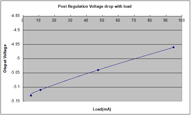
However post regulation the output voltage only drop 0.17v over the tested range.
Stripboard:
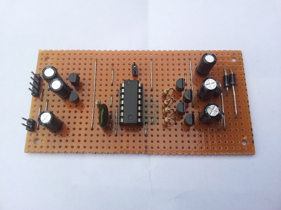
Once the design was finalised it was transferred onto strip-board for soak testing.
%20-%20small.png)
As Built:
The circuit was then load tested for several days and continued to function correctly.
|