Main Page | Projects IndexGallery Index | Data & Infomation


Workshop Alarm System

Overview


In order to trial a number of modules that have already been developed, namely the MicroMite GPC Board, I2C 4x4 keypad, DFPlayer Interface, 4 Bit Input Board, 3.3V & 5V Regulator Board and the Dual MOSFET Switch. 

A project was devised that would combine them all.

The project selected was a workshop alarm system, this could be soak tested in situ for an extended period and should highlight any issues that continuos operation may produce.

The system will have the following features: 

  • 4 Inputs - Entry Door sensor, Fire Alarm Sensor, PIR A and PIR B
  • 2 Outputs - Bell and Strobe
  • I2C keyboard, RTC and LCD display
  • Audio speech presented to the user via the MP3 DFPlayer board controlled via MCU COM#1
  • User settings and codes will be held in MCU flash.
  • A 30 entry event log is maintained by the alarm so that the activity can be reviewed,this will be available via the LCD or via a data dump to the terminal port.

Alarm System Menu Structure


The alarm system code was written in MiroMite Basic as this is the native language of the boot loader that resides within the GPC, additionally it provides a method or rapidly developing and debugging code in very short time scales. 

The program itself has a series of menus that allow the user to navigate the system, these are described below.

Main:

When the system is first switched on the alarm defaults to the main menu, from here the user is able to select 3 sub menus (each of which are discussed in reveres order below). The RTC time and date are also presented live to this screen.


Main 3 - Settings:

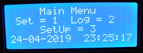
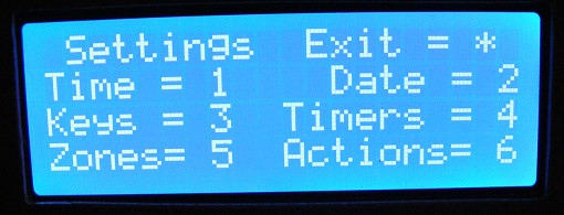
By selecting option 3 on the main menu, the system settings menu can be accessed. From here all the configurable elements of the alarm can be changed.
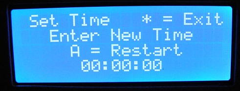
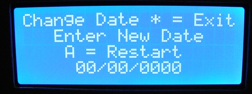
Settings 1 & 2:

For example from the setting menu, the time and date of the RTC can be altered.
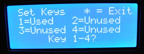
 

Settings 3:

Additionally as the system can have up to 4 keys, option 3 allows all of these keys to be modified. On startup key 1 defaults to '1234'. This code can obviously be changed and the active codes are written to MCU flash.
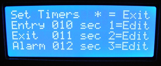
Settings 4:

The Alarm has 3 timers Entry, Exit and Alarm. These default to the short values below on first startup. Once again edited values are written to MCU flash.
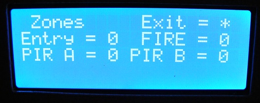
Settings 5:

The state of the Zones and Sensors can be monitored via option 5 on the settings menu. Note all these inputs are fail safe i.e. a closed input contact is shown as a zero or inactive state.
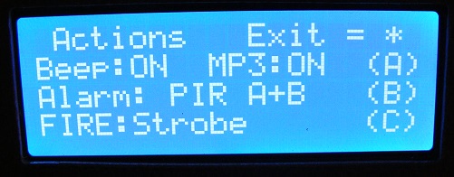
Settings 6:

Option 6 on the settings menu allow the user to silence the key beeps and MP3 sound playback if desired. in addition to this the user can also change the alarm action of the PIRs.

For example PIR A+B means that the alarm will trigger if either of the PIR sensors are active or PIR A&B means that both PIR sensors must be active at the same time in order to trigger an alarm.

Finally the FIRE input can be set so that when it becomes active the siren, strobe or both outputs can become active.
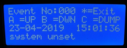
 

Main 2:

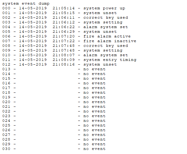
Back on the main menu the 50 entry event log can be accessed and viewed, if required the logs output can be dumped to the serial terminal port for viewing/printing (see below).
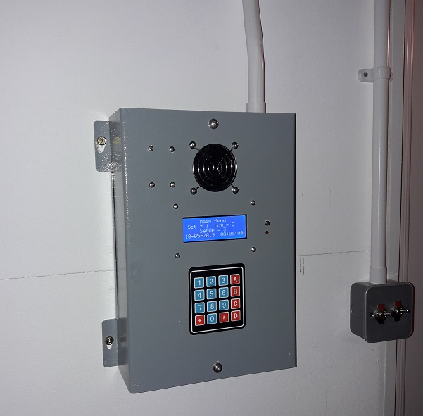
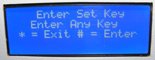
Main 1:

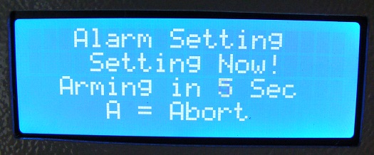
From option 1 on the main menu, if one of the 4 system keys are entered at the prompt the system will enter 'exit timing' mode and once this is complete the alarm system will switch into 'system set' mode .

Exit Countdown after key entry

System Armed and Waiting For Event

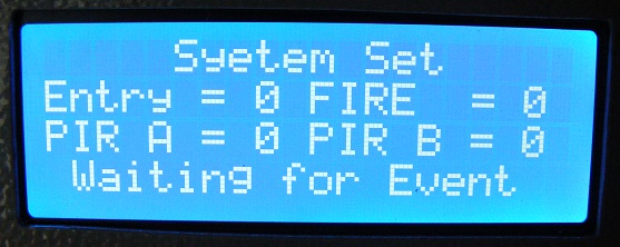
Once the system is set, it can exit this mode in one of three ways.

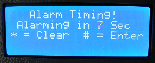
Outcome 1 - Entry detector triggered:

If the entry sensor is triggered the system enters 'Entry Countdown' mode, during this time the user must enter one of the 4 system keys to unset the system. Failure to do so will switch the system to 'Alarm Active' Mode.  

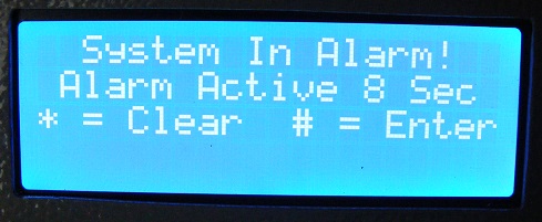
Outcome 2 - Alarm Active:

If a correct key is not entered during the entry time or PIR A+B or PIR A&B are triggered the system will enter into 'alarm' mode for the alarm period. At the end of this time the system will reenter the 'system set' mode where it can be re triggered and go back into alarm.

Outcome 3 - correct code entered:

If the entry time is not exceeded and the correct code is entered the alarm returns to an 'unset' state and the user is taken back to the main menu.
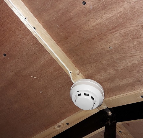
Fire Alarm Active:

At any time if the FIRE input should become active then the system will enter the FIRE active mode.


Construction and As Built


The program was configured to use the IO of the MicroMite GPC as follows:

GPC Input / Output MicroMite Pin
Entry Sensor 2
Fire Sensor 3
PIR A Sensor 5
PIR B Sensor 4
Case Tamper Switch 6
DFPlayer playback_busy 15
Sounder 26
LED Lamp (flashes when set) 25
Bell 24
Strobe 23
DFPlayer Com1 Tx 21

Once initial testing of the code was complete the system was constructed into a suitable metal enclosure so that final testing and commissioning could be undertaken.


Additional parts:

These additional boards were used in the construction of the alarm, all of which are simple to construct or purchase.

- 2x fused supply boards

- A transistor driven pizzo buzzer

- USB to serial converter module

- Tamper mirco-switch


Installation:

The system was installed and tested in early May 2019, various elements of the alarm are pictured below:


Software:

The software uses a group of mp3 files that are saved onto an SD card within the DFPlayer,these are listed below.

These are called upon within the program in order to give user feedback, for example on line 107 of the listing the instruction 'if mp3_action then play_mp3(3,1)' instructs the subroutine to issue the startup command 'Alarm System Ready' if 'mp3_action' the Boolean that allows MP3 playback is set.

03

001

Intruder Alarm System

Alarm System Ready


002

Intruder Alarm System

Alarm System Unset


003

Intruder Alarm System

Alarm System Set


004

Intruder Alarm System

Alarm System Arming Please Exit


005

Intruder Alarm System

Intruder Detected


006

Intruder Alarm System

Please enter password key to deactivate alarm


007

Intruder Alarm System

Fire alarm active please evacuate area


008

Intruder Alarm System

System tamper triggered (Unused)


As mentioned earlier the software also allows a data dump of the log file to be made via the terminal port, this dump appears as below:


Links:

Click here to download the associated project files:

- MicroMite Workshop Alarm Code V1.07 - Here

- SD card zip files -  Here 

(Unzip and place the '03' directory onto a blank SD card formatted to FAT32 for the DFPlayer)