Main Page | Projects IndexGallery Index | Data & Information


Sunrise Google Wireless

Overview


Call me old fashioned but I have always wanted a Bush sunrise radio with the circular tuning dial and integral ring light. However as these days I mostly consume audio content via a phone app or via a Google home mini, I suspected that it would hardly be used.

Then one day I thought why can't I combine the Bush radio and Google home mini to make a retro smart speaker. I could then Bluetooth link it to my phone in order consume content that could not easily be streamed.

After some initial development, I found that the hardest problem will be to drive the ring light whenever the Google home mini is activated. Initially I experimented with monitoring current consumption in order to determine when the speaker was active. This did work to some degree, however this approach proved too erratic to be reliable.

In the end, the only reliable way seemed to be to tap into the speaker and monitor for any activity. There are lots of examples on the net that discusses how to access the speaker and install an external output socket, so for that reason I won’t cover this aspect of the project here.

Instead, I will concentrate on how to build the various boards that allow the Google home mini to operate and still maintain the original functionality of the Bush radio.

Warning! – This project requires the construction of a new mains power supply for the BUSH radio if you have never worked on this type of circuit before or are not confident/competent to do so, you should use an external incapsulated wall wart transformer in place of the one used. This should be a 1 to 2 Amp / 15 to 18 Volt class 2 transformer, if a DC transformer is used the bridge rectifier of PSU1 can be removed.


The Project


 The the project required the conduction of 3 new boards, these are namely:

- PSU Part 1 - A linear power supply and ring light driver board.

- PSU Part 2 - A 5V switch mode power supply board for the Google mini.

- A Google ring light control board – to detect when the Google speaker was active.

These work as follows:

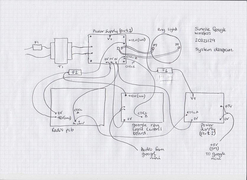
PSU 1 replaces the original transformer of the radio and feeds a regulated +12V into the radio’s low voltage AC input. This 12V is also passed to the ring light control board in order to monitor the google home mini for activity.

When the radio is switched on, originally the radio PCB provided power to a set of lamps inside the ring light of the radio. There are two sets of terminals for the lamps on the radio PCB and these are marked up as 'AC Lamp' or 'DC Lamp', and either may have been used in the original radio.

However, as we are supplying DC to the radio PCB, now when it is switched on one of the 'AC Lamp' terminal will provide a DC voltage that can be uses to switch on a ring light circuit and perform other functions as required, in the diagram below I have tagged up this new control line as CTRL A. In practice the lower of the two AC input terminals on the radio PCB is connected via the radio on/off switch to the left-hand 'AC Lamp' terminal when it is viewed in the upright position.

When the radio is switched on CTRL A is used to switch a transistor driver in PSU 1 that illuminates two white LEDs inside the ring light, CTRL A is also fed to PSU 2 and in turn deactivates the supply to the Google mini. Leaving the google mini and switch mode power supply turned on when the radio was on created so much interference the LW & MW bands of the Bush radio were unusable, however by switching these off all of the bands of the Bush radio could be used.

If the radio is off and the switch mode power supply and google mini are on, whenever the google mini generates any sound this is detected via the Google ring light control board which in turn generates a second ring light control signal CTRL B, this is fed to the ring light driver circuit on PSU 1 which lights the ring light.

Finally 3 fuses have been used in the final design F1 @250mA and F2 & F3 @1A.
 

PSU Part 1


The first power supply is a standard linear circuit consisting of a bridge rectifier, pi network and regulator. The board also has a NPN transistor that is used to switch on the ring light whenever CTRL A or CTRL B are active. 

It is probably worth mentioning here that in order to diffuse the light from the LEDs the lens of the white LEDs were filed off in the final assembly as it was found that this gave an overall neater effect.

Circuit diagram:


Component layout:


PSU Part 2

 Circuit diagram:

Component layout:


Google ring light control

Circuit diagram:

Component layout:

Demo & Links


 The the project required the conduction of 3 new boards, these are namely:

- PSU Part 1 - A linear power supply and ring light driver board.

-